Our Physics Journey

Measuring a Glass Slab indirectly.

How can we determine the length, breadth and thickness of a rectangular glass slab without simply measuring it directly? Instead of relying on just one technique, we explored several ideas from physics — projection, optics, photography and parallax.

The Question

One glass slab. Three dimensions. Four methods.

Our objective was to determine the three dimensions of a rectangular glass slab using indirect methods. Each method approached the same problem from a different physics concept.

01

Shadow

Using light and geometrical projection.

02

Optical

Using image formation and refraction.

03

Photography

Turning pixels into physical dimensions.

04

Parallax

Using apparent displacement.

05

Free Fall

The attempt that didn't quite work.

01
First Approach

Shadow Method

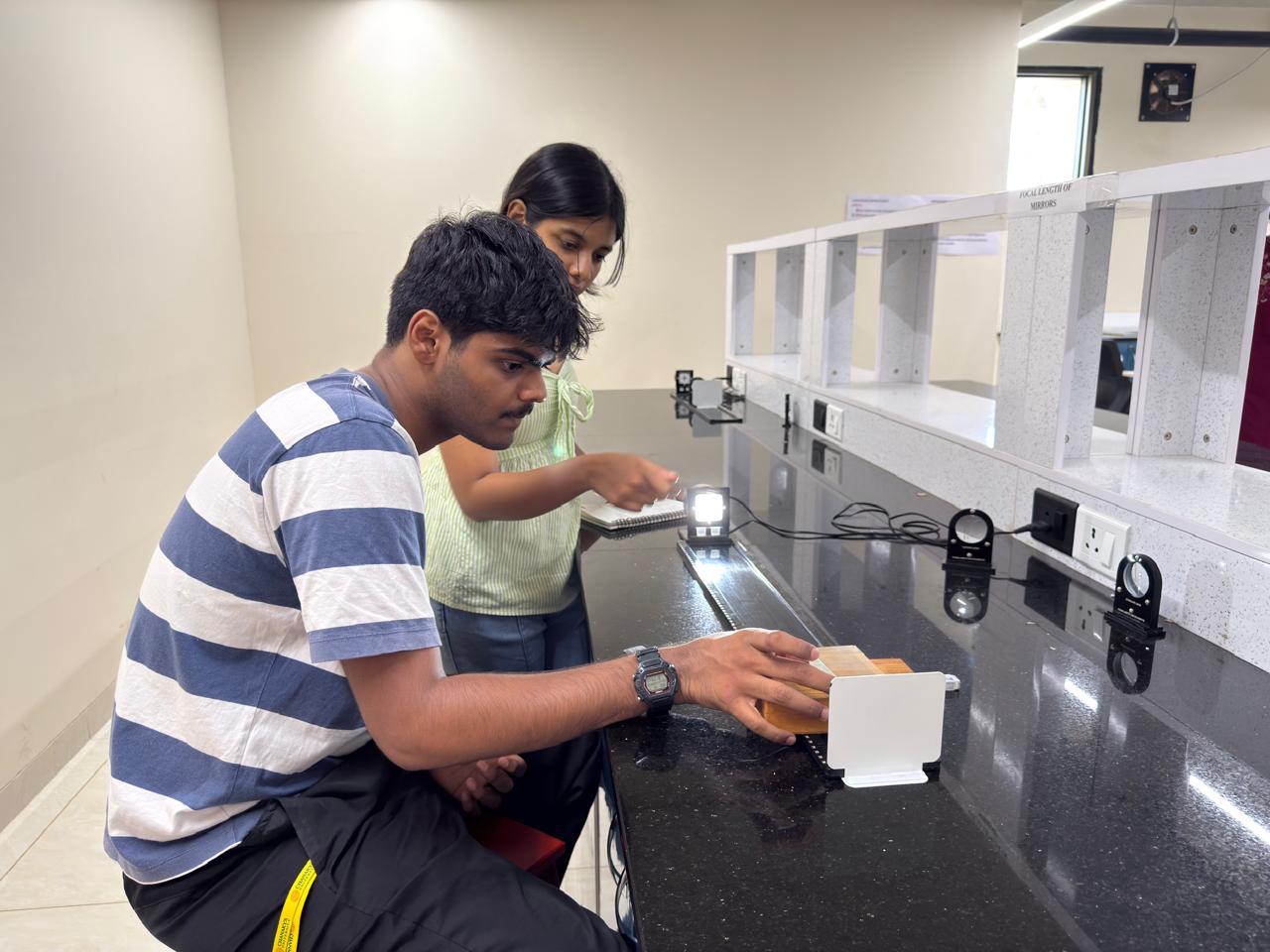
Our first idea was simple: if light travels in straight lines, could the shadow of the glass slab reveal its dimensions?

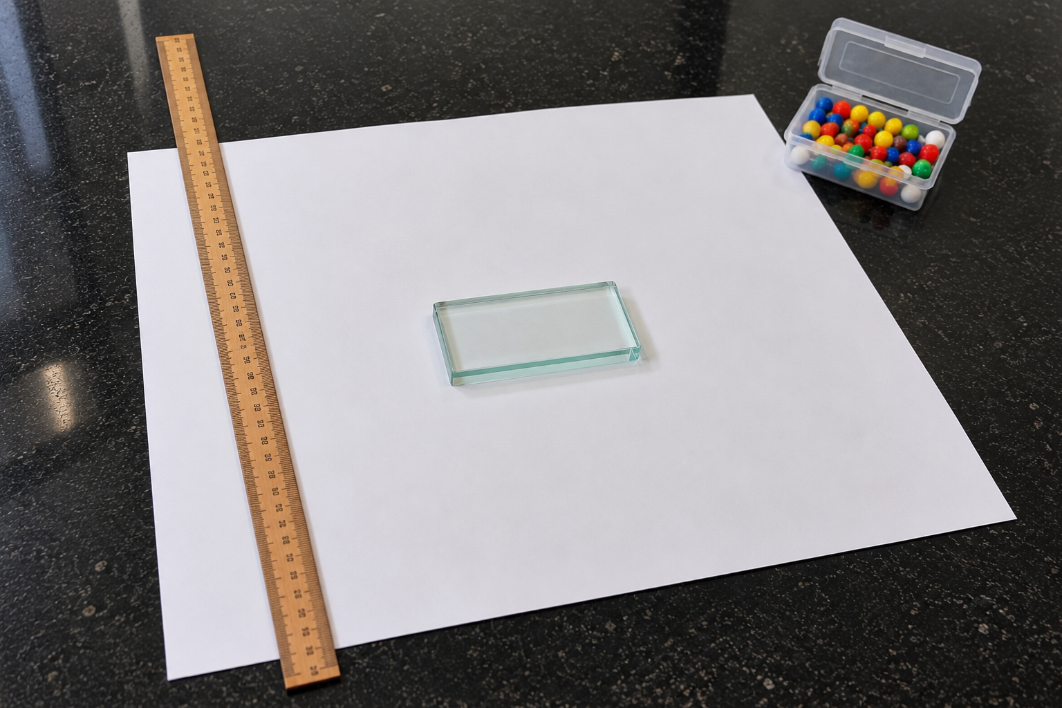
Shadow Method — Apparatus 📸
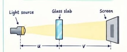
Shadow method apparatus
Shadow Method — Apparatus

Physics Principle

In a uniform medium, light travels approximately in straight lines. When light falls on an object, a shadow or projection is formed. By comparing this projection with a known reference and applying geometrical similarity, the dimensions of the glass slab can be estimated.

Apparatus

  • Glass slab
  • Light source
  • Screen
  • Reference object
  • Metre scale
  • Stand/support

Procedure

  1. Place the glass slab in a fixed position.
  2. Illuminate it using the light source.
  3. Obtain a clear projection on the screen.
  4. Use a known reference for calibration.
  5. Measure the projected dimensions.
  6. Apply the geometrical relationship.
  7. Repeat for the required orientations.

Why does it work?

The shadow is a geometrical projection. Its dimensions depend on the dimensions of the slab and the geometry of the light-source and screen arrangement.

Length — L

The long projected edge can be compared with a known reference to determine the length of the glass slab.

Breadth — B

The transverse projected dimension can similarly be calibrated using the reference object.

Thickness — t

By changing the orientation of the glass slab, its smaller thickness dimension can also be obtained from the projection.

General relationship
Unknown dimension ≈ Known reference dimension × (Projected slab dimension ÷ Projected reference dimension)

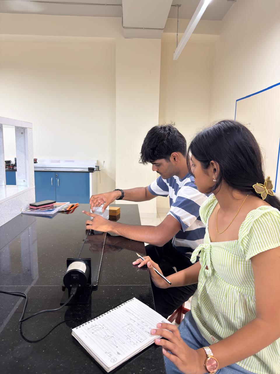
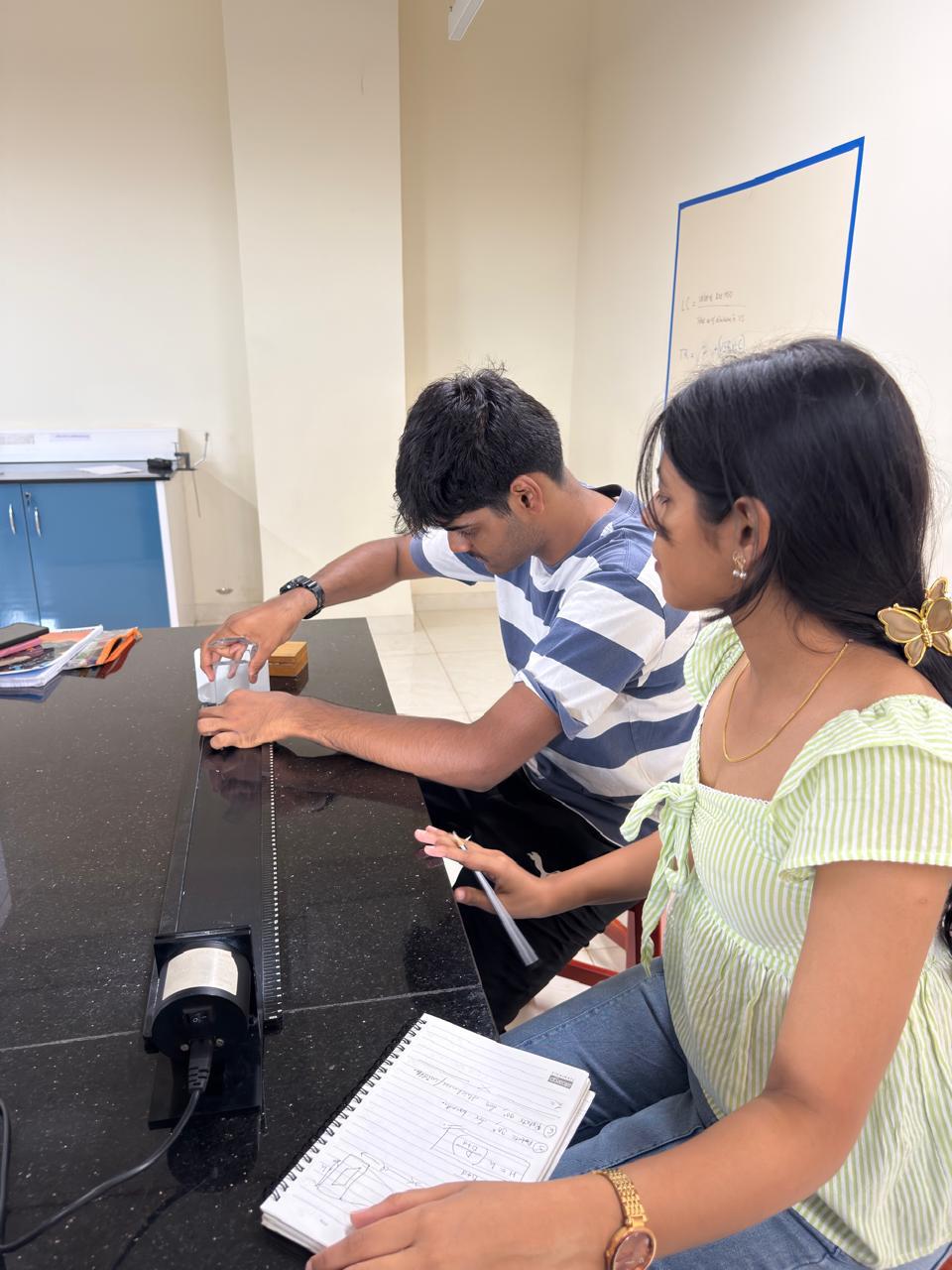
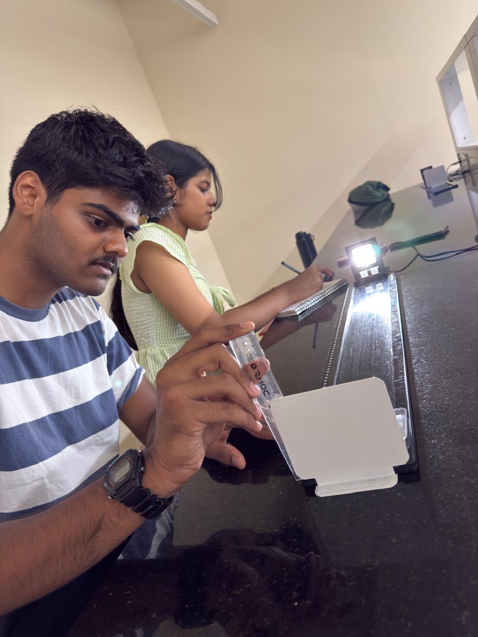
Our Shadow Experiment 📸
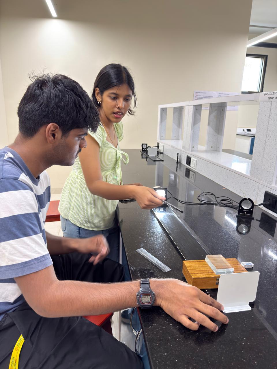
Shadow method photo 1
Shadow Method — Photo 1
Shadow method photo 2
Shadow Method — Photo 2
Shadow method photo 3
Shadow Method — Photo 3
Shadow method photo 4
Shadow Method — Photo 4
Shadow method photo 5
Shadow Method — Photo 5
02
Second Approach

Optical Method

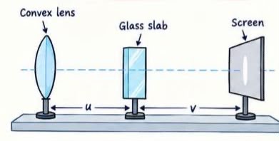
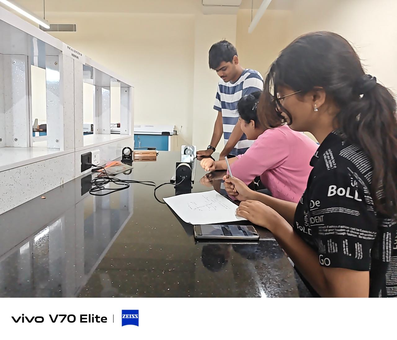
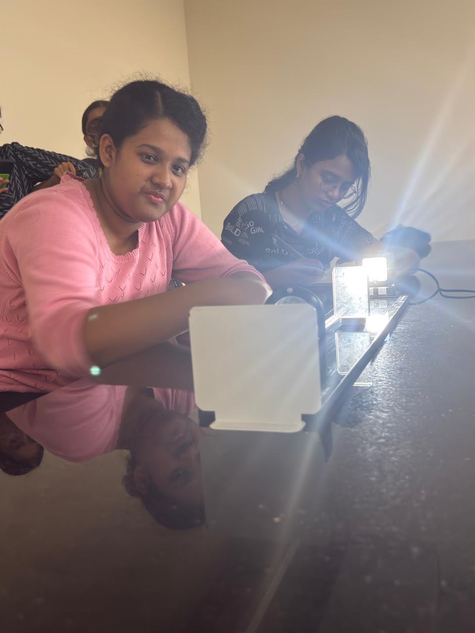
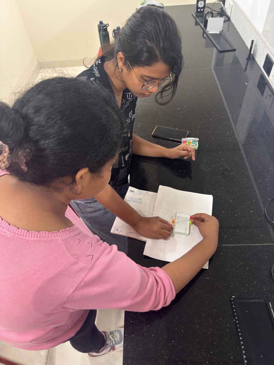
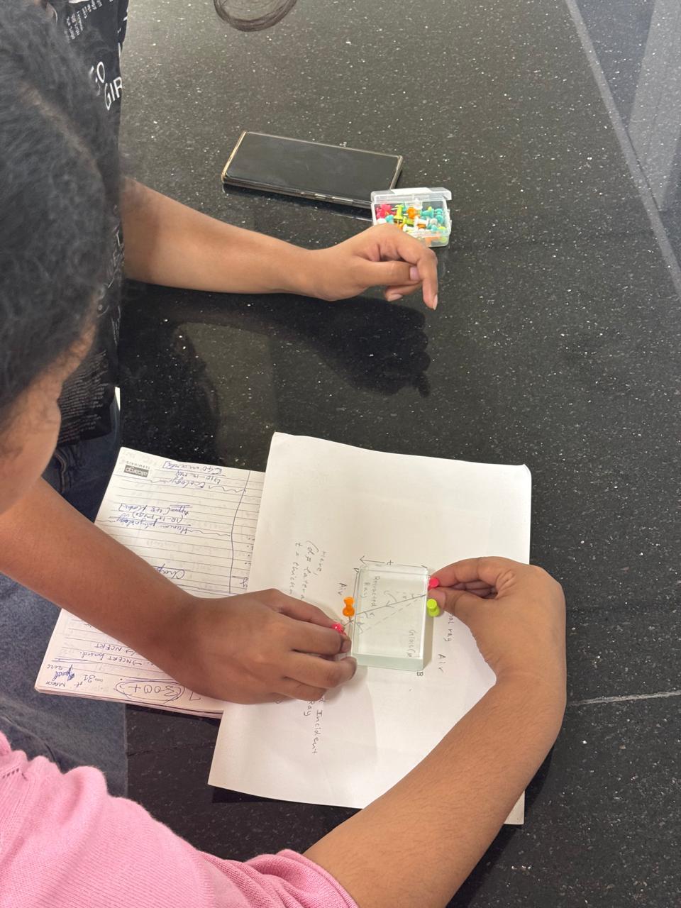
After shadows, we moved into geometrical optics and explored how refraction and image formation could provide information about the glass slab.

Optical Method — Apparatus 📸

Optical method apparatus
Optical Method — Apparatus

Physics Principle

When light passes from one medium to another, its speed changes and its direction may change. This phenomenon is called refraction. A plane-parallel glass slab produces a measurable optical displacement that can be related to its thickness.

Apparatus

  • Convex lens
  • Glass slab
  • Screen
  • Scale
  • Object
  • Optical support

Procedure

  1. Set up the convex lens and screen.
  2. Obtain a sharp image.
  3. Record the relevant positions.
  4. Introduce the glass slab.
  5. Observe the optical displacement.
  6. Measure the required distances.
  7. Apply the optical relationship.

Key Idea

Instead of physically measuring every edge, we use the behaviour of light and the resulting image displacement to obtain information about the slab.

Length — L

The longitudinal geometry of the setup can be used to obtain the required dimension.

Breadth — B

The slab can be oriented so that the transverse dimension is represented in the optical arrangement.

Thickness — t

The apparent displacement caused by refraction can be related to the actual thickness.

Optical relationships
n₁ sin i = n₂ sin r

For a plane-parallel slab: d = t · sin(i − r) / cos r

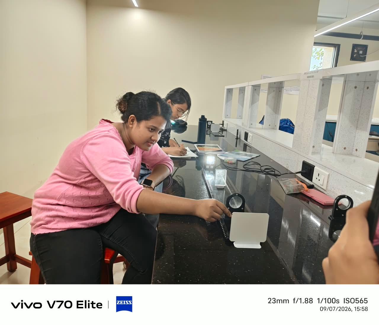
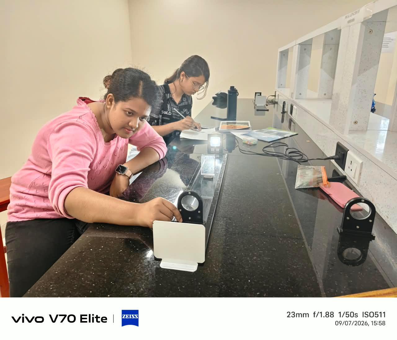
Our Optical Experiment 📸
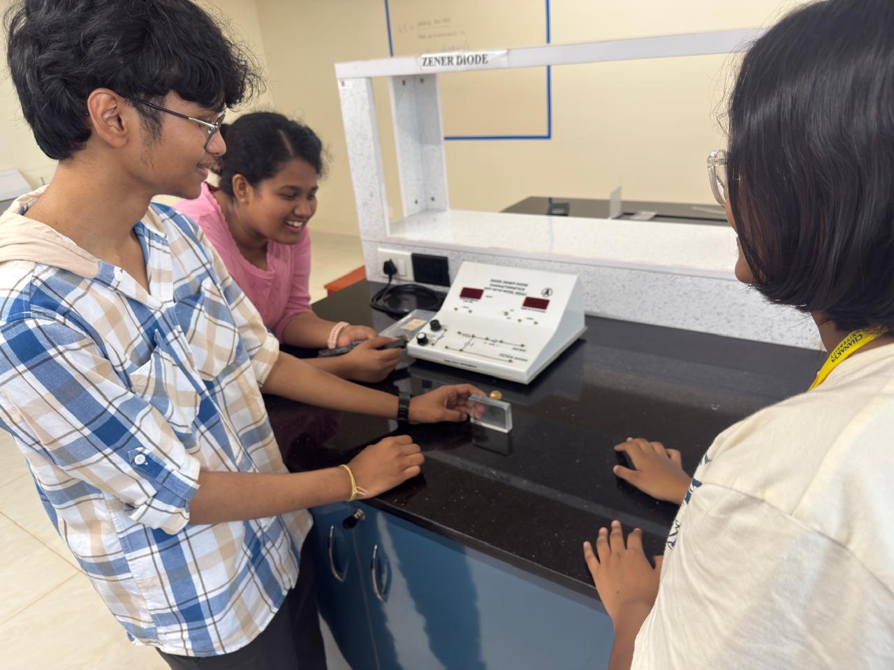
Optical method photo 1
Optical Method — Photo 1
Optical method photo 2
Optical Method — Photo 2
Optical method photo 3
Optical Method — Photo 3
Optical method photo 4
Optical Method — Photo 4
Optical method photo 5
Optical Method — Photo 5
03
Third Approach

Photography / Pixel Method

Then came a more modern approach: instead of measuring the glass slab directly, we measured it inside a photograph.

Physics Principle

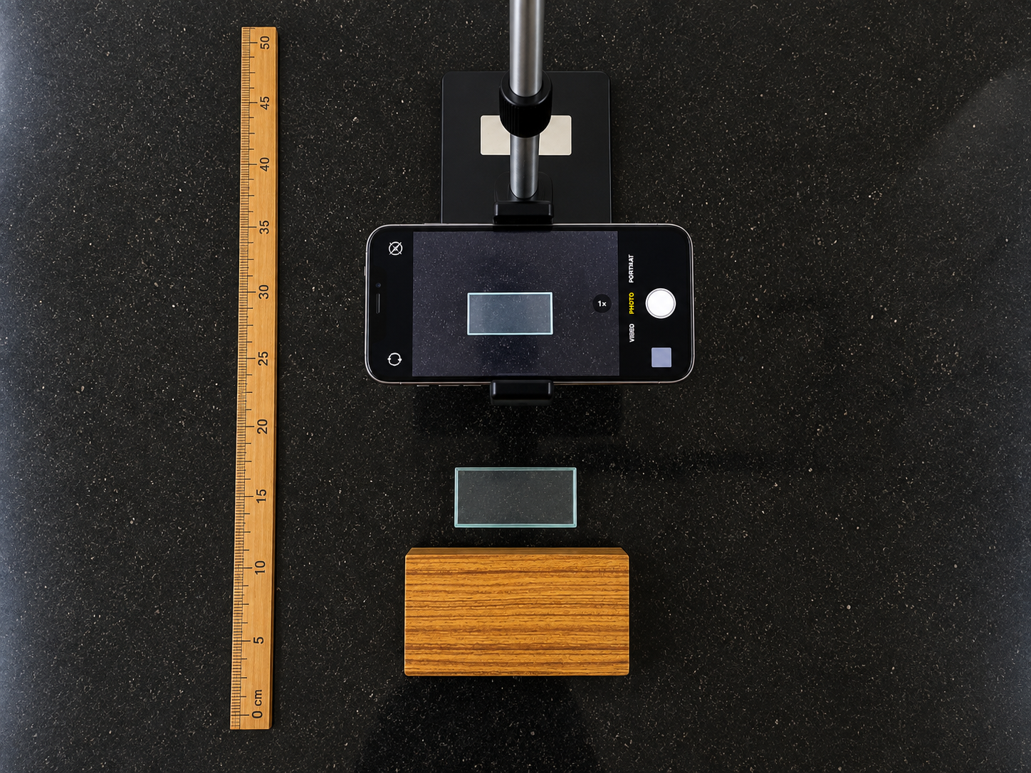
A digital photograph consists of pixels. If an object of known physical size is placed in the same image as the glass slab, the ratio between its actual size and pixel size provides a scale factor. The pixel dimensions of the slab can then be converted into physical dimensions.

Pixel Calibration
Scale = Actual size of the reference object ÷ The size of the reference object in pixels

Actual slab dimension = Slab dimension in pixels × Scale

Photography Method — Apparatus 📸

Photography method apparatus
Photography Method — Apparatus

Apparatus

  • Glass slab
  • Smartphone/camera
  • Reference object
  • Stable flat surface
  • Pixel measurement software

Procedure

  1. Place a known reference object near the slab.
  2. Keep both approximately in the same plane.
  3. Take a clear photograph.
  4. Measure the reference object in pixels.
  5. Measure the glass slab in pixels.
  6. Calculate the scale.
  7. Convert pixels into physical units.

Important Points

  • Keep the camera perpendicular.
  • Minimise perspective distortion.
  • Use sharp edges.
  • Keep the reference object close.
  • Repeat measurements.

Length — L

Measure the long edge in pixels and multiply it by the calibrated physical scale.

Breadth — B

Measure the shorter top-view dimension and use the same pixel-to-length calibration.

Thickness — t

Use a front or side photograph in which the thickness is clearly visible.

Our Photography Experiment 📸
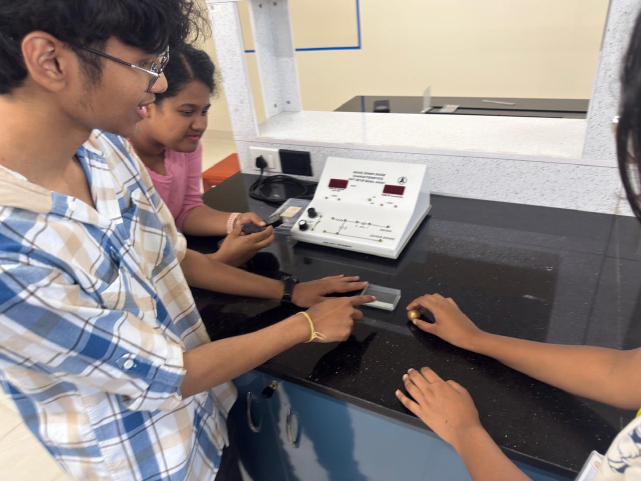
Photography method photo 1
Photography — Photo 1
Photography method photo 2
Photography — Photo 2
Photography method photo 3
Photography — Photo 3
Photography method photo 4
Photography — Photo 4
Photography method photo 5
Photography — Photo 5
04
Fourth Approach

Parallax Method

Our final main approach changed the position of the observer rather than the glass slab.

Parallax Method — Apparatus 📸

Parallax method apparatus
Parallax Method — Apparatus

Physics Principle

Parallax is the apparent displacement of an object when it is viewed from different positions. When the observer moves through a known baseline, the apparent position of the object changes. This displacement can be analysed using geometry.

Apparatus

  • Glass slab
  • Eye/camera
  • Reference object
  • Known baseline
  • Scale
  • Stable support

Procedure

  1. Fix the glass slab.
  2. Choose a suitable reference.
  3. Observe from the first position.
  4. Record the apparent position.
  5. Move through a known baseline.
  6. Observe again.
  7. Determine the apparent displacement.
  8. Apply the appropriate geometry.

Key Idea

The glass slab remains stationary. The observer moves, producing an apparent shift that contains information about the geometry.

Length — L

The apparent positions of the relevant edges can be compared from different viewpoints.

Breadth — B

A lateral viewing arrangement can be used to analyse the transverse dimension.

Thickness — t

The apparent displacement between surfaces can be used to infer the slab's thickness.

Parallax Geometry
θ ≈ apparent displacement ÷ observation distance

The exact final equation depends on the geometry of the setup.

Our Parallax Experiment 📸
Parallax method photo 1
Parallax — Photo 1
Parallax method photo 2
Parallax — Photo 2
Parallax method photo 3
Parallax — Photo 3
Parallax method photo 4
Parallax — Photo 4
Parallax method photo 5
Parallax — Photo 5
05 · The Plot Twist

Then came Free Fall.

After completing our four main approaches, we also considered a free-fall method. The idea was to use the motion of a falling object and timing information to obtain a measurement indirectly.

We couldn't find the right ball for the experiment.

And even apart from the ball, several practical difficulties would have affected the accuracy of the method.

  • Ball size: The ball is not a mathematical point, so its size introduces uncertainty in locating its centre.
  • Release uncertainty: The object has to be released without an unintended push.
  • Timing error: For a short fall, human reaction time can become significant.
  • Alignment: The motion needs to follow the intended path.
  • Measurement uncertainty: Small errors in distance and time can affect the calculated result.
  • Repeatability: Multiple trials would be required for a reliable measurement.

Evidence of the Attempt 📸

Free fall attempt 1
Free Fall — Photo 1
Free fall attempt 2
Free Fall — Photo 2
Free fall attempt 3
Free Fall — Photo 3
Free fall attempt 4
Free Fall — Photo 4
Free fall attempt 5
Free Fall — Photo 5
06 · Recorded Observations

Our Observation Tables

After going through the methods, we can now look at the observations collected during the experiment.

01

Shadow Method — Dimensions

Dimension Image Size (cm) u (cm) v (cm) Measured Dimension (cm)
Length (L) 4.7 27.5 19.0 8.46
Breadth (B) 3.4 22.8 16.8 6.05
Thickness (t) 1.0 24.5 19.5 1.83
Shadow Result: L = 8.46 cm • B = 6.05 cm • t = 1.83 cm
02

Optical Method — Observation

Observation Image Size (cm) u (cm) v (cm) Measured Value (cm)
A 4.7 29.5 1.5 8.46
B 3.4 23.8 13.3 6.05
T 1.0 27.5 15.0 1.83
Optical Result: 8.46 cm • 6.05 cm • 1.83 cm
03

Photography / Pixel Method

Dimension Reference Actual (cm) Reference Pixels Glass Slab Pixels Scale (cm/pixel) Calculated (cm)
Length 9.30 1374.1 1179.7 0.00677 7.98
Breadth 9.30 1422.0 787.6 0.00654 5.15
Thickness 4.30 596.1 320.4 0.00721 2.31
Photography Result: L = 7.98 cm • B = 5.15 cm • t = 2.31 cm
R

Reference Dimensions of the Glass Slab

Dimension Reference Value Unit
Length (L) 8.0 cm
Breadth (B) 5.3 cm
Thickness / Height (t) 2.3 cm

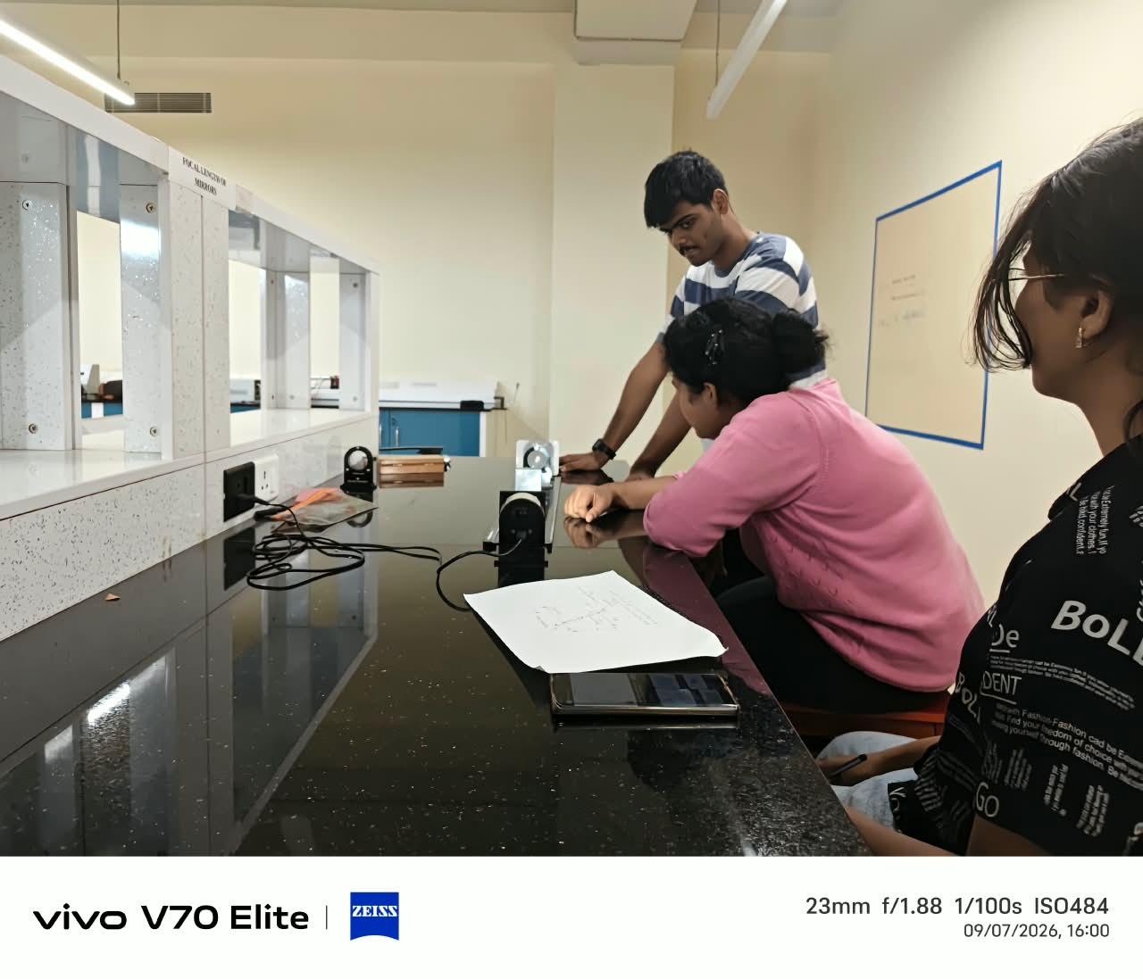
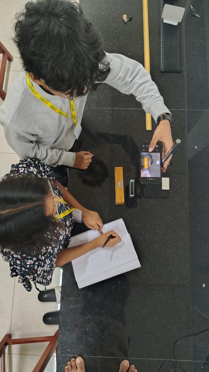
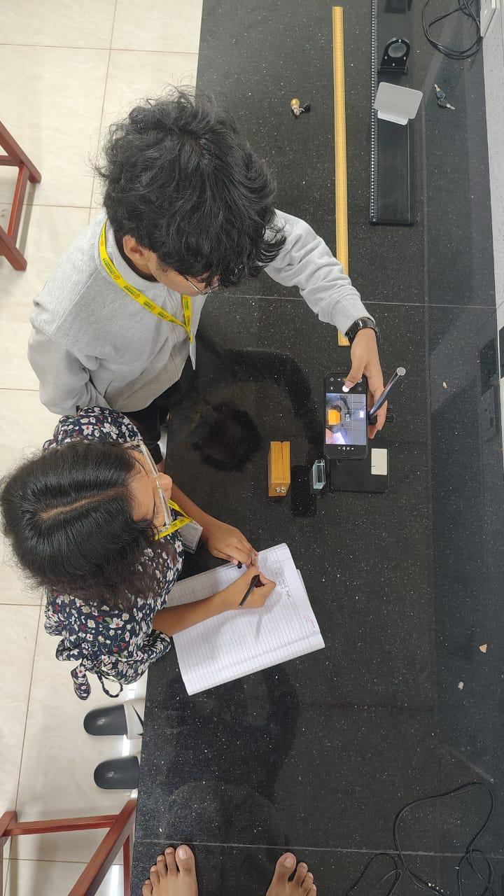
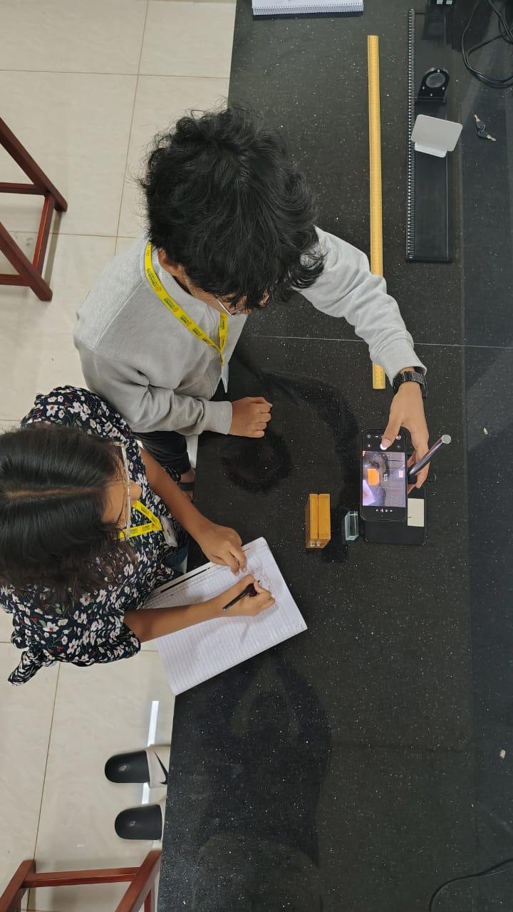
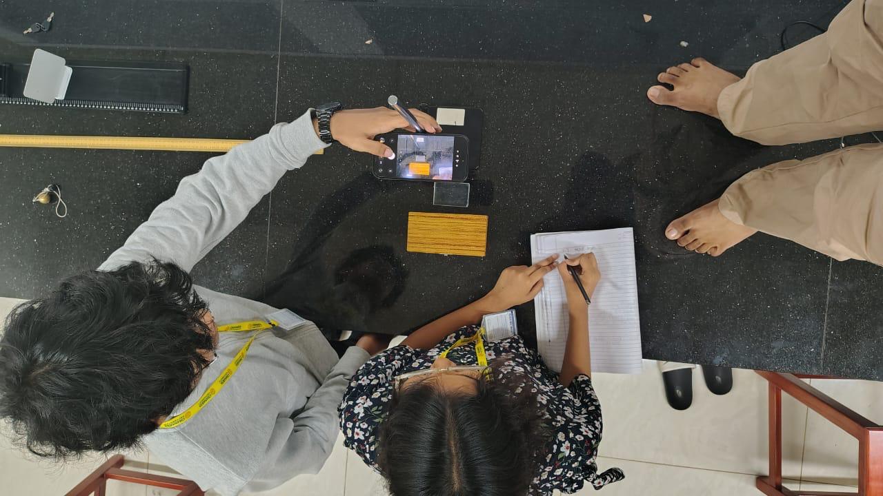
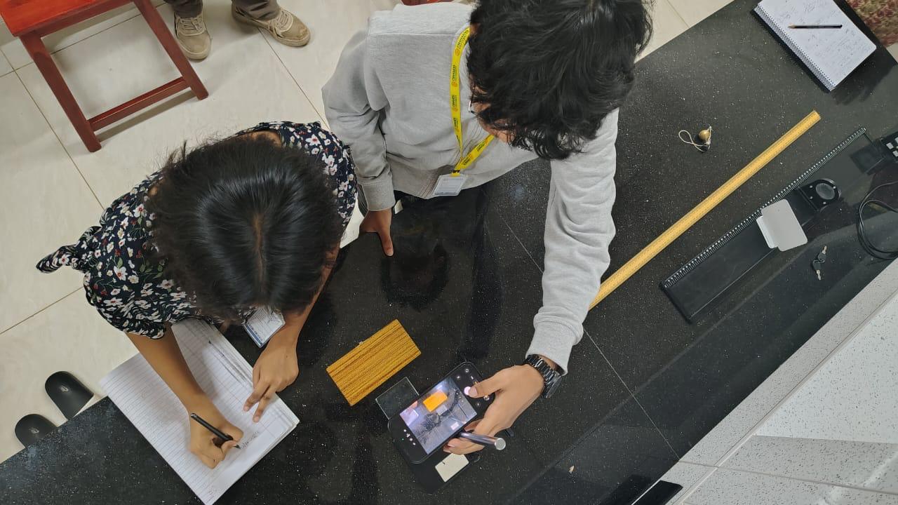
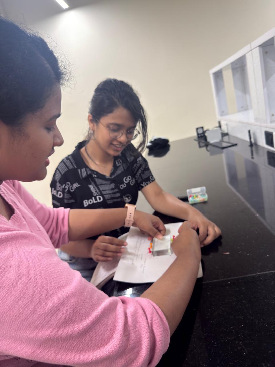
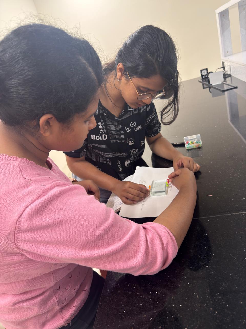
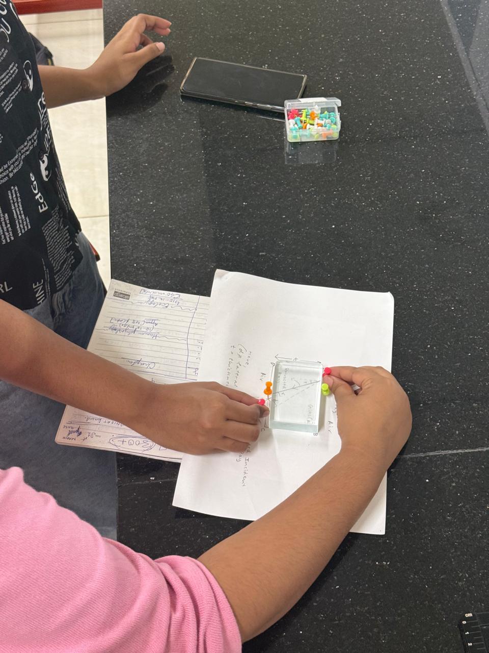
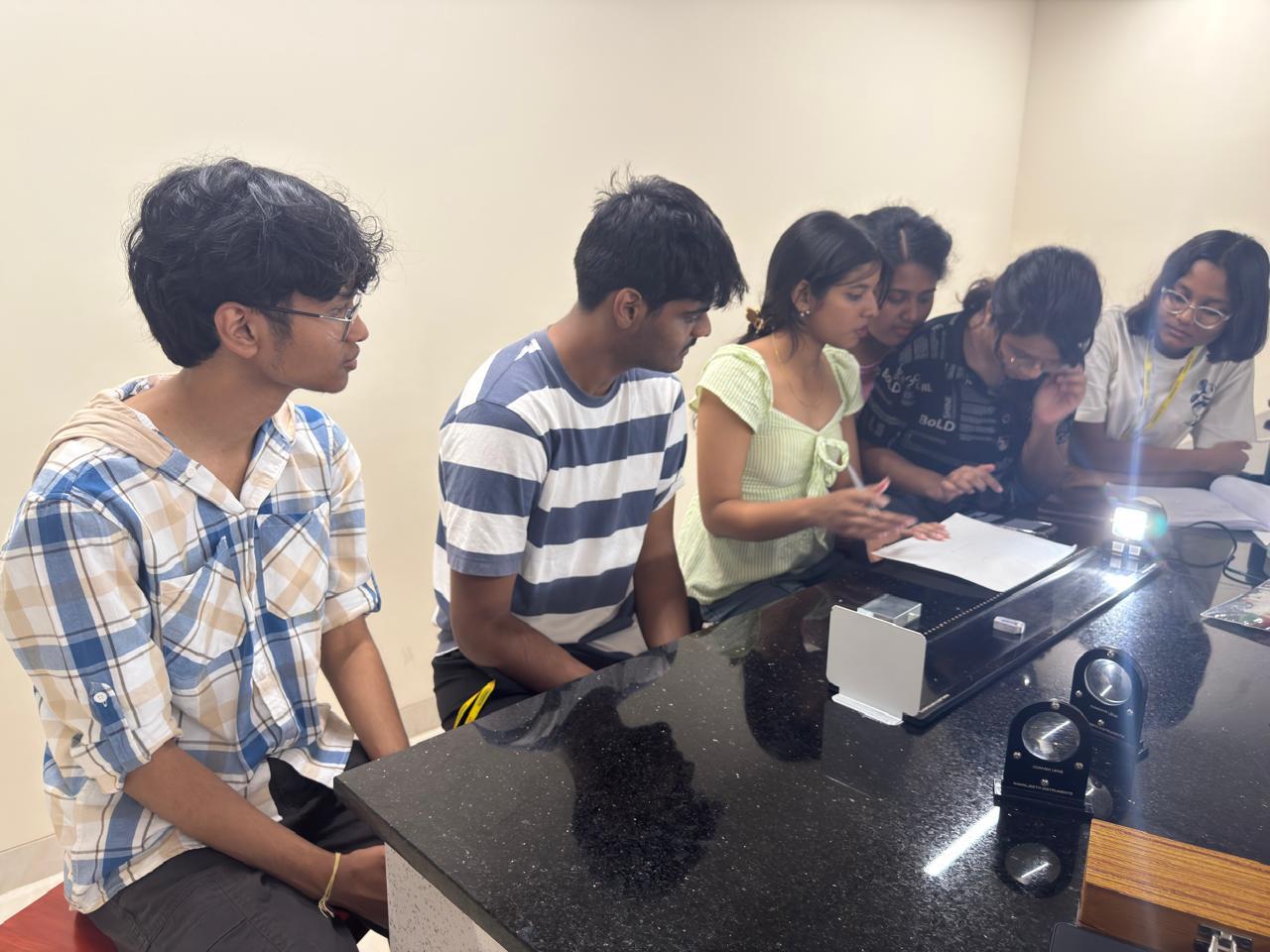
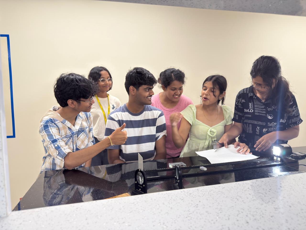
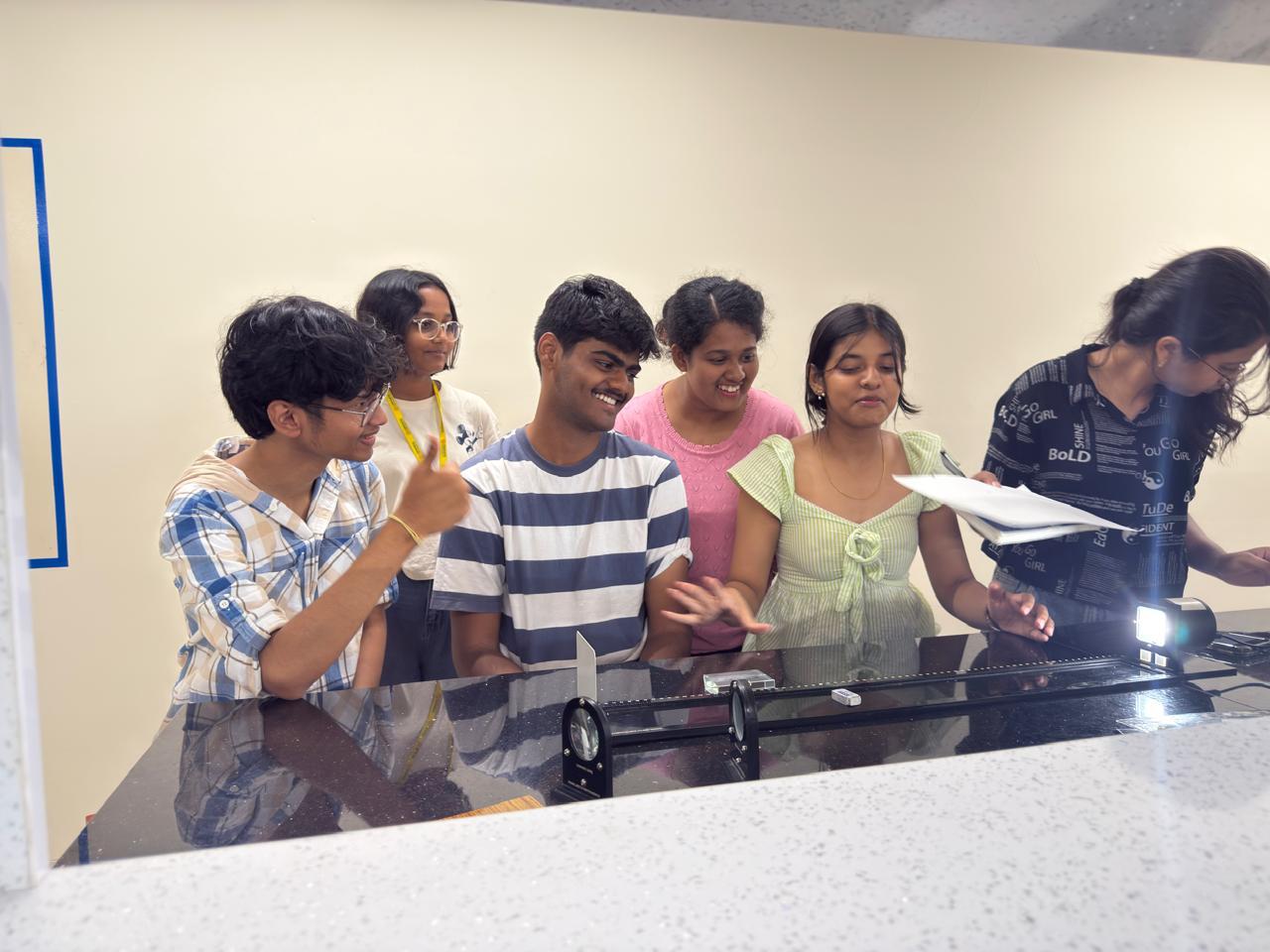
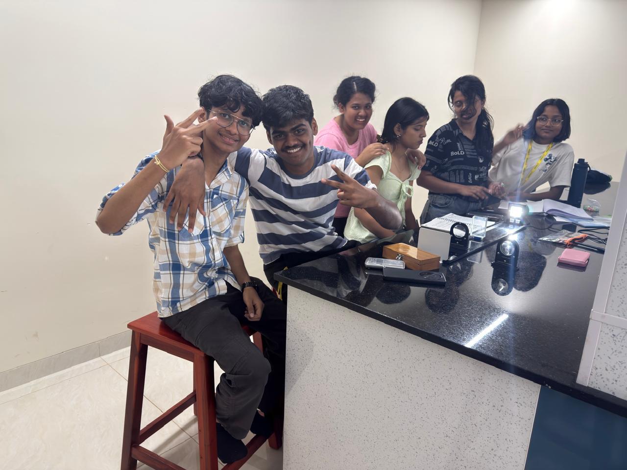
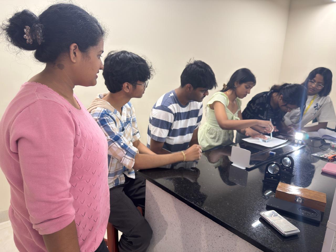
The Team Behind the Experiment 📸
Group photo 1
Group Photo 1
Group photo 2
Group Photo 2
Group photo 3
Group Photo 3
Group photo 4
Group Photo 4
Group photo 5
Group Photo 5
07 · Error Analysis

How close were our measurements?

Percentage Error

Percentage Error = |Measured Value − Reference Value| ÷ Reference Value × 100

Our reference dimensions were: Length = 8.0 cm, Breadth = 5.3 cm, Thickness = 2.3 cm .

Method Dimension Reference (cm) Measured (cm) Percentage Error
Shadow Length 8.00 8.46 5.75%
Breadth 5.30 6.05 14.15%
Thickness 2.30 1.83 20.43%
Optical Length 8.00 8.46 5.75%
Breadth 5.30 6.05 14.15%
Thickness 2.30 1.83 20.43%
Photography Length 8.00 7.98 0.25%
Breadth 5.30 5.15 2.83%
Thickness 2.30 2.31 0.43%
Note: The Photography measurements are recorded directly in centimetres. Therefore, the measured values are compared directly with the reference dimensions in centimetres.

Sources of Experimental Error

  • Alignment errors in the experimental setup.
  • Difficulty identifying the exact edges of the glass slab.
  • Perspective distortion in photographs.
  • Reference-object calibration uncertainty.
  • Parallax during visual observation.
  • Limited image resolution.
  • Human positioning and measurement errors.
Same light.
Different perspectives.
Physics
is everywhere
📏

Tape Measure

And after all that physics... sometimes the simplest solution wins. 😭

JOURNEY COMPLETE

Thank You

That brings our experimental journey to an end.

We started with a simple glass slab and turned it into a full exploration through shadows, optics, photography, parallax, calculations — and even a free-fall attempt that had its own plot twist.

”

The real lesson? Physics isn't always about finding the easiest way to get an answer. Sometimes, it's about discovering how many different ways you can get there.

💡

Curiosity

Started the journey

⚙

Exploration

Found new perspectives

☆

Learning

Goes beyond answers

Thank you for giving us this amazing oppurtunity. ✨

⌂ Back to Home

SAME QUESTIONS. BRIGHTER PERSPECTIVE.